
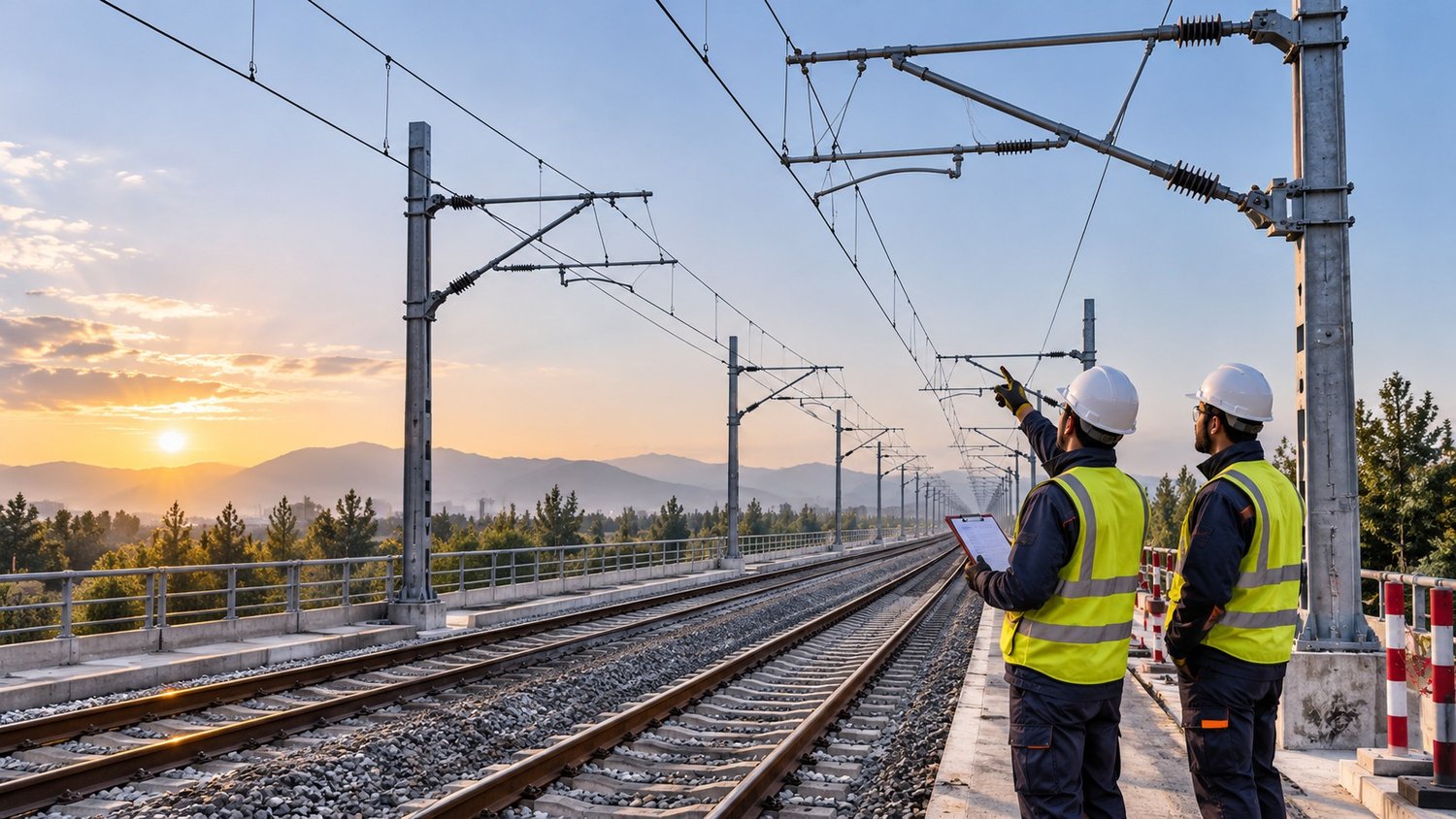
A stable electrical supply is one of the foundations of safe and reliable metro and electrified railway operation. Trains draw traction power from the rail infrastructure, but performance depends on much more than voltage choice or equipment installation: conductor geometry, connections, fleet compatibility, safety, environmental conditions and maintainability must be considered throughout design and delivery.
The two widely used approaches are overhead contact systems (OCS) and third rail. Overhead systems provide electricity to a pantograph through a contact wire or a rigid conductor above the track; third-rail systems place a conductor beside the running rails for collection by a shoe on the train. Neither technology is universally preferable: each requires a project-specific engineering assessment.
Images are conceptual illustrations of technologies and processes, not documentary photographs of TTRA project delivery.
1. How does electricity reach the train?
Railway traction power begins with electricity received and converted at the appropriate substations. Feeders and the traction distribution system deliver it to the contact conductor; a train collects it through a pantograph or a collector shoe. The electrical circuit is completed through a return-current arrangement defined by the traction power design. Running rails form part of this return circuit in many systems, but traction return, protective earthing and equipotential bonding are different engineering functions.
Reliable performance requires more than electrical continuity. Current collection quality, voltage drop, protection coordination, electrical sectioning, maintenance access and control of stray currents in DC systems must be engineered together. The traction power network is an integrated subsystem of the railway, not simply an assortment of individual components.
2. Flexible overhead contact systems (Flexible OCS)
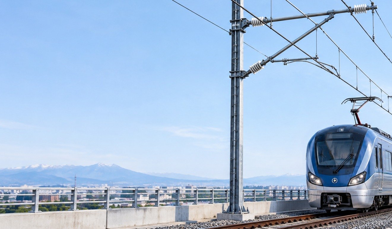
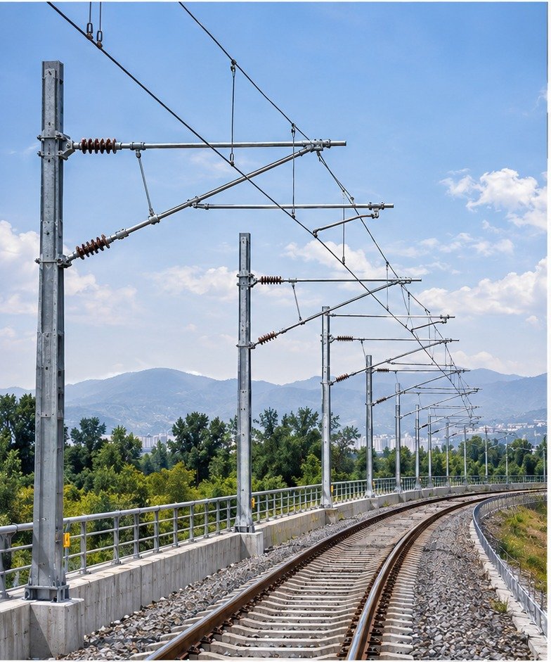
In a flexible OCS, the contact wire runs above the track. In many designs, a messenger wire, droppers and support arms maintain the contact wire in its required geometry. The train pantograph slides against the underside of that wire to supply power to the traction equipment.
Typical components include masts and foundations, cantilevers and registration arms, insulators, contact and messenger wires, droppers, fittings, tensioning devices, electrical connections and sectioning equipment. Their layout depends on route geometry, design speed, climate, curve radii and installation constraints.
Flexible systems can accommodate a range of spans and alignments. However, wire tension, geometry, thermal movement and periodic inspections must be controlled closely. A small error repeated across successive supports can reduce contact quality and accelerate wear.
3. Rigid overhead contact systems (Rigid OCS)
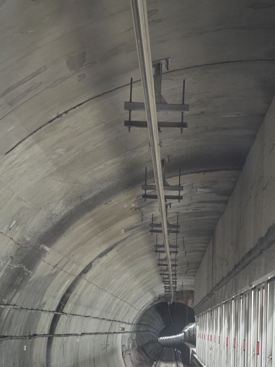
A rigid OCS usually uses a rigid conductive profile mounted to the tunnel roof or another overhead support, with the contact wire retained inside the profile. It remains above the train and transfers current to the pantograph. Rigid overhead conductor rail must not be confused with the third rail installed beside the running track.
Rigid systems are often considered for restricted-clearance areas such as selected tunnels and covered structures. Support spacing, profile alignment, joints and expansion allowances, lateral contact-wire deviation, flexible-to-rigid transitions and electrical bonding all require precise design.
Although the structural arrangement can appear simpler than a suspended catenary, performance depends on accurate installation of anchors, profiles and connectors. Misalignment or discontinuity may affect pantograph passage and require difficult remedial work in tunnels.
4. Overhead system installation: from approved drawings to final adjustment
1. Site readiness and approved documents: Check structural drawings, track geometry, mast locations, adjacent equipment, access for machinery and interfaces with other disciplines. Resolve field changes through the approved engineering process.
2. Structures and hardware: Verify foundations and fixing points, then install supports, cantilevers, insulators and fittings according to approved manufacturer instructions. Record bolt torque, component orientation, protective coatings and material traceability.
3. Wiring or rigid-profile installation: Protect conductors against handling damage. For flexible systems, coordinate wiring with the tensioning and adjustment plan; for rigid systems, pay particular attention to joint alignment.
4. Geometry measurement: Verify contact-wire height, stagger, conductor tension, dropper positions and special locations, including curves, turnouts and transition zones, against approved tolerances.
5. Inspection and corrective action: Keep measured results, inspection photographs and non-conformance records current. Visually completing the installation does not by itself mean the line is ready for service.
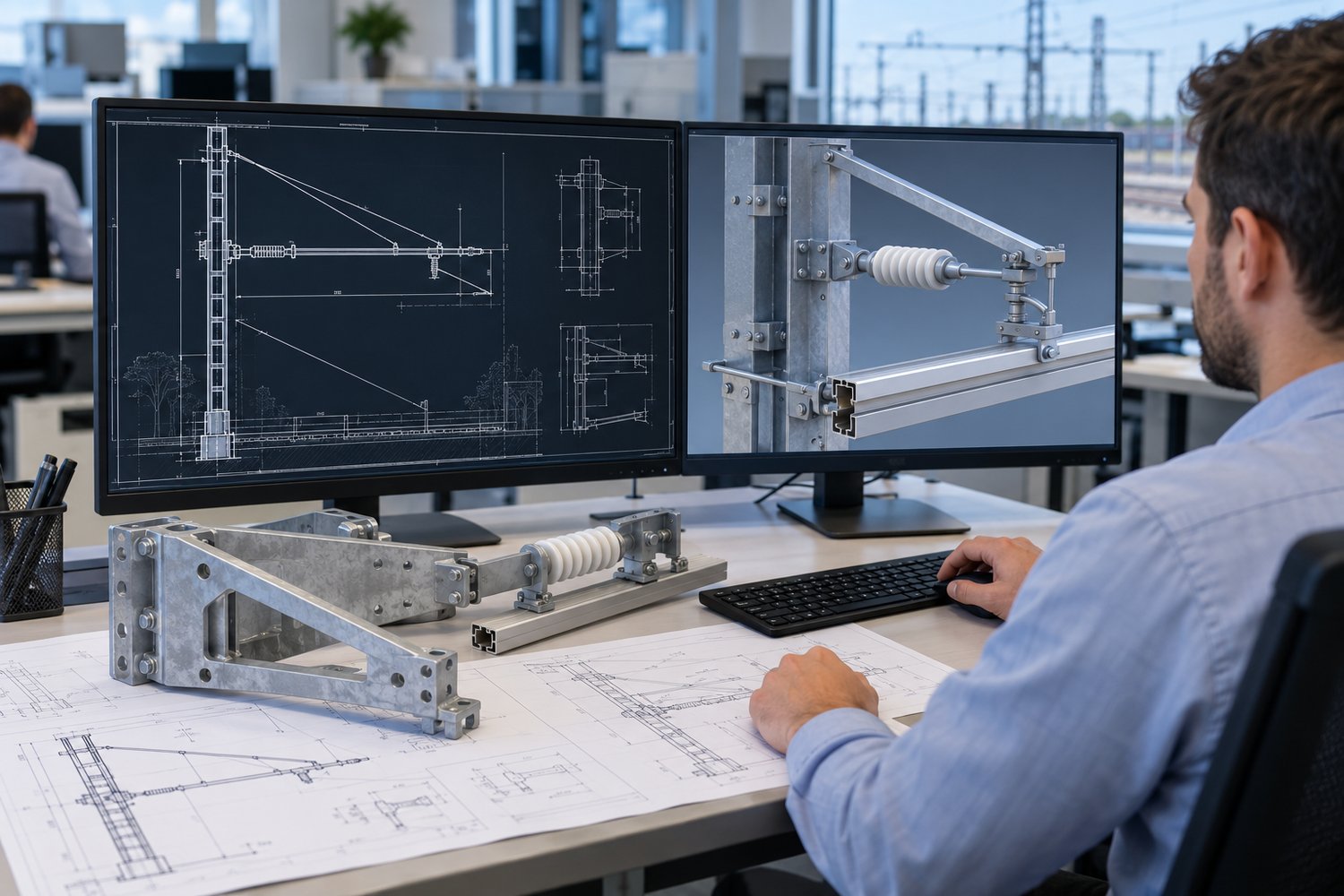
5. Why geometry and wire tension are critical to OCS
Current collection is a dynamic interaction between the moving pantograph and the contact wire or rigid conductor. Contact-wire height, stagger, vertical gradient, wire tension and mechanical response must be assessed as an interacting system rather than as isolated parameters.
In auto-tensioned systems, counterweights or tensioning devices and the freedom of movement of associated parts help maintain the specified tension over the design temperature range. Sectioning points, overlaps, changes of system type and nearby structural equipment deserve special inspection.
Measurements also need to be repeatable: the track reference, equipment, measurement method, environmental conditions and exact location should be documented. A number without a known reference and location offers limited value to engineering decisions.
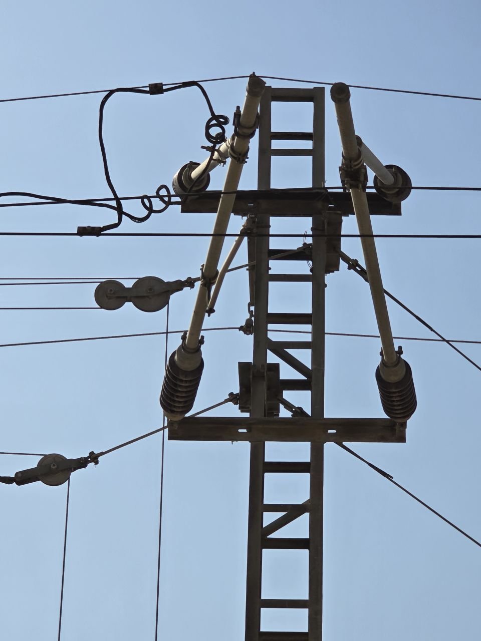
6. How does the third rail work?
A third-rail system places a separate conductive rail alongside the running rails. Instead of collecting current overhead, the train uses a collector shoe that slides against the conductor rail. This approach is used in many urban rapid-transit systems and commonly uses DC traction supply.
Its principal elements include conductor rails, supports and brackets, insulators, protective covers where specified, feeders and electrical joints, ramps at section ends, expansion joints, isolating arrangements and vehicle collector shoes. Design must also account for turnouts, crossings, special track sections and gaps in the conductor rail.
Current can be collected from the top, bottom or side of the rail, according to system design. Each configuration has different conductor profiles, cover requirements, shoe geometry and access restrictions. Equipment and rolling stock cannot simply be transferred between systems without a compatibility assessment.
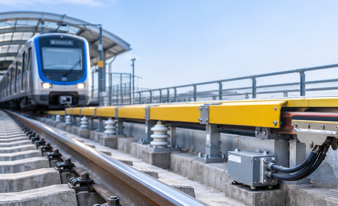
7. Third-rail installation and quality control
Third-rail installation starts with verifying the track reference and the position of the running rails. The conductor rail offset and elevation must match the approved design along straights, curves and vertical transitions. The quality of support brackets and insulating bases directly affects conductor stability.
Inspect electrical connections and contact resistance, rail continuity, expansion assemblies, end ramps and required gaps at interruptions and route changes. For covered installations, check that the protective cover is correctly fitted, that the collector shoe has sufficient clearance and that inspection access is maintained.
Checking visual straightness alone is not enough. Insulator condition, cable termination quality, electrical clearances, collector-shoe movement envelopes and thermal effects require mechanical and electrical verification.
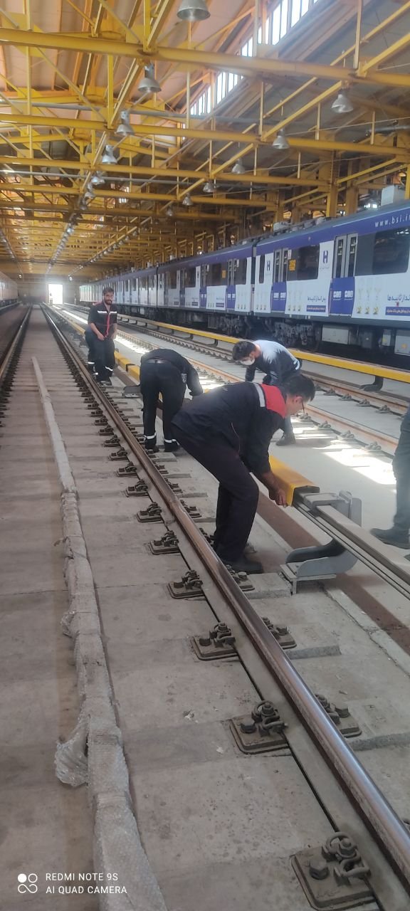
8. Electrical safety of overhead systems and third rail
Both arrangements involve hazardous traction voltages. Overhead equipment introduces proximity risks above the track; third-rail equipment adds contact risks near track level. A protective cover reduces exposure but does not make a live system inherently safe.
Construction and maintenance must take place under authorised work permits and operating coordination, using the approved isolation, verification of de-energisation and protection against unexpected re-energisation. Earthing or other protective measures must follow the requirements of the specific system. Train movements, stored energy and alternative feeds belong in the risk assessment.
For DC traction systems, return-current management, bonding and stray-current control are particularly important. Incorrect bonding or earthing can create electrical faults and corrosion; therefore protective connections must follow the approved design.
9. Preventive maintenance and root-cause diagnostics
For OCS, regular inspections may assess contact-wire and pantograph strip wear, tensioning equipment, alignment, droppers, insulators, electrical joints and sectioning locations. Unusual wear, geometry movement, loose joints and heat damage should be recorded and prioritised by risk.
For third rail, inspect conductor contact surfaces, collector-shoe wear, ramps, joints, cracked or contaminated insulators, damaged covers, overheated connections and water ingress. Arcing or poor collection may reflect interactions between infrastructure and rolling stock rather than one defective part.
Effective troubleshooting moves from symptoms to root causes. Failure reports, historical measurements, exact locations and vehicle equipment conditions help avoid repetitive short-term repairs.
10. Comparing OCS and third rail in practice
Conductor position: OCS transmits power from above the train to a pantograph; the third rail is mounted alongside the track and connects to a collector shoe.
Space requirements: overhead systems require suitable space above the train. Third rail can offer clearance advantages in some low tunnels, but it introduces additional access and safety constraints at track level. Rigid OCS may also be suitable for certain restricted-height areas.
Maintenance: for OCS, attention centres on overhead geometry and pantograph interaction. For third rail, conductor surfaces, shoes, insulators, covers and gaps are key.
Safety and final selection: both require strict energy control and permits. Selection must consider rolling-stock compatibility, power capacity, speed, alignment, tunnel constraints, lifecycle cost, maintainability and future expansion. No single solution is optimal for every project.
11. Multidisciplinary coordination and quality assurance
Railway electrification work requires close coordination among traction power, track, structures, signalling, telecommunications, safety and operations teams. Final rail position, geometric tolerances, lineside equipment, maintenance access and possession windows must be agreed before work begins.
For each activity, the inspection and test plan should identify hold points, approving authorities, measuring equipment, acceptance criteria and records. Handover documentation normally includes as-built drawings, test results, component traceability, non-conformance reports and an outstanding-items list.
Quality assurance is not limited to discovering defects at the end. Its purpose is to prevent errors before they become concealed by later stages, reducing rework and improving the traceability of engineering decisions.
12. Testing, commissioning and handover
After installation and adjustment, final mechanical and electrical checks must follow the approved project test plan. Depending on the design, these checks can include final geometry, conductor continuity, protective connections, appropriate insulation tests, sectioning operation and verification of system interfaces with rolling stock.
Commissioning should proceed in controlled stages with clear responsibilities and operations coordination. Open items and non-conformances must be resolved or formally assessed before final authorisation. Successful handover includes the installed assets as well as records, maintenance procedures, test history and required training.
13. Conclusion: sound design, precise delivery and dependable maintenance
Flexible OCS, rigid overhead conductor rail and third rail represent distinct methods of collecting traction current. Each has advantages, limitations and specific requirements; sustainable performance depends on decisions made across design, installation, adjustment, safety and maintenance.
The shared engineering principle is continuous compliance with the approved design, supported by recorded quality-control results. Good equipment cannot compensate for poor installation, just as accurate installation cannot replace a dependable maintenance plan.
TTRA – Tamin Tavane Raily Co. – provides railway and metro electrification solutions, including overhead contact systems and third-rail arrangements. This technical article is published to support engineering understanding, installation quality and informed technology selection.
Quick comparison of three technologies
| Feature | Flexible OCS | Rigid OCS | Third rail |
|---|---|---|---|
| Current collection | Overhead contact wire | Overhead rigid conductor | Conductor beside track |
| Collector | Pantograph | Pantograph | Collector shoe |
| Typical application | Varied alignment and spans | Selected height-limited sections | Selected metro networks |
| Inspection focus | Wire tension and geometry | Profile alignment and connections | Contact surfaces, insulation and cover |